|
|
Deturbulated Detached Flow at 80 Knots Indicated Airspeed
|
(click to enlarge images)
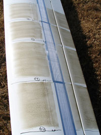
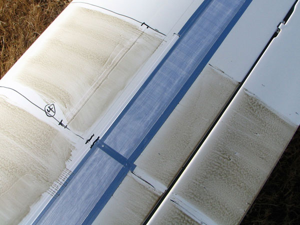
| After Flight - Overview |
|
|
|
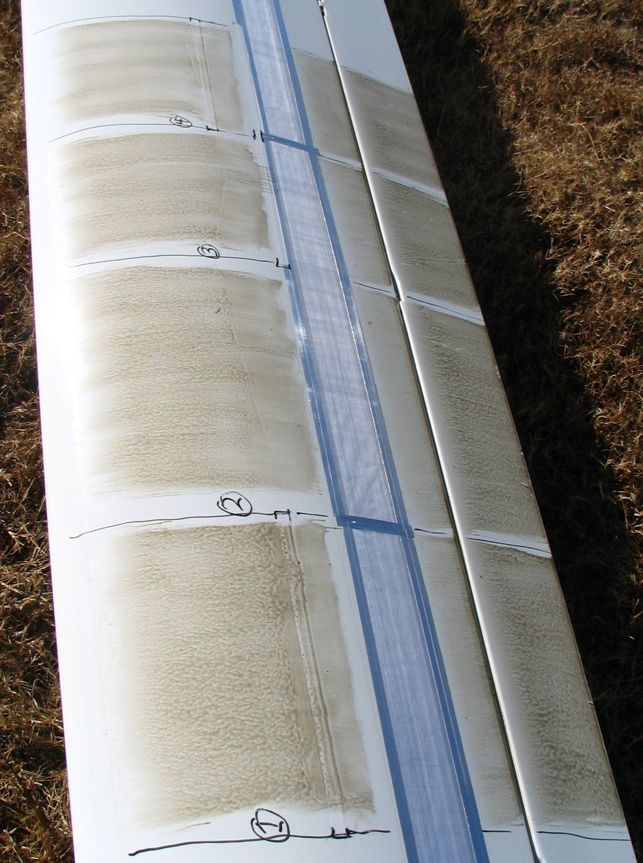
Top of Outboard Left Wing
Sections 1-4
|
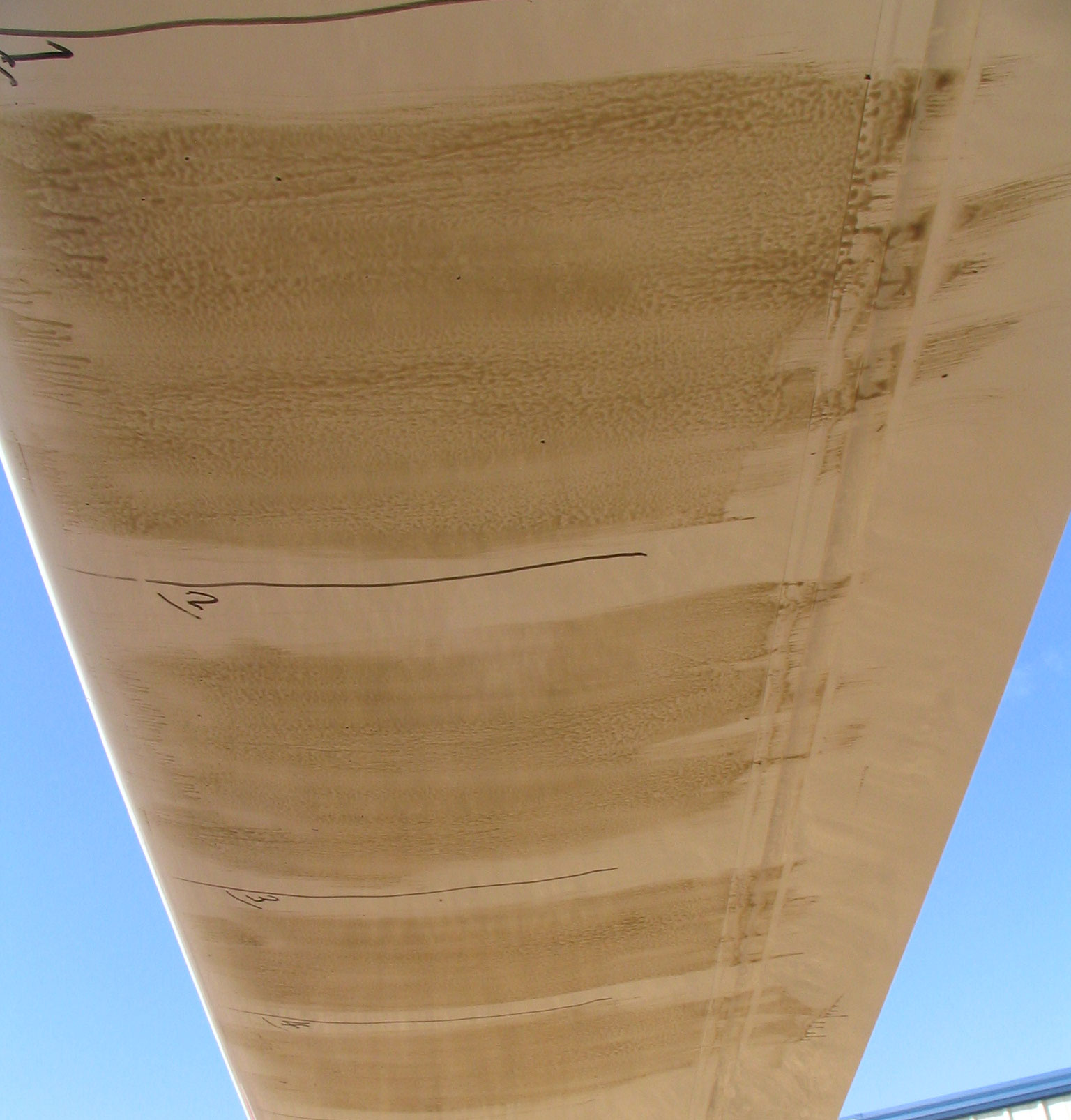
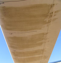
Bottom of Outboard Left Wing
Sections 1-4
|
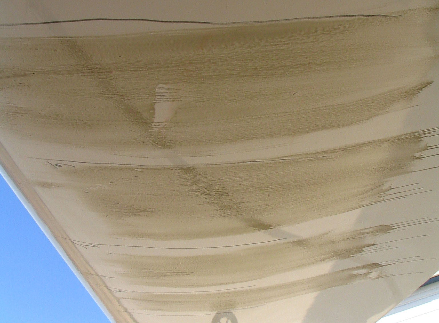
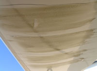
Bottom of Inboard Right Wing
Sections 5-8
|
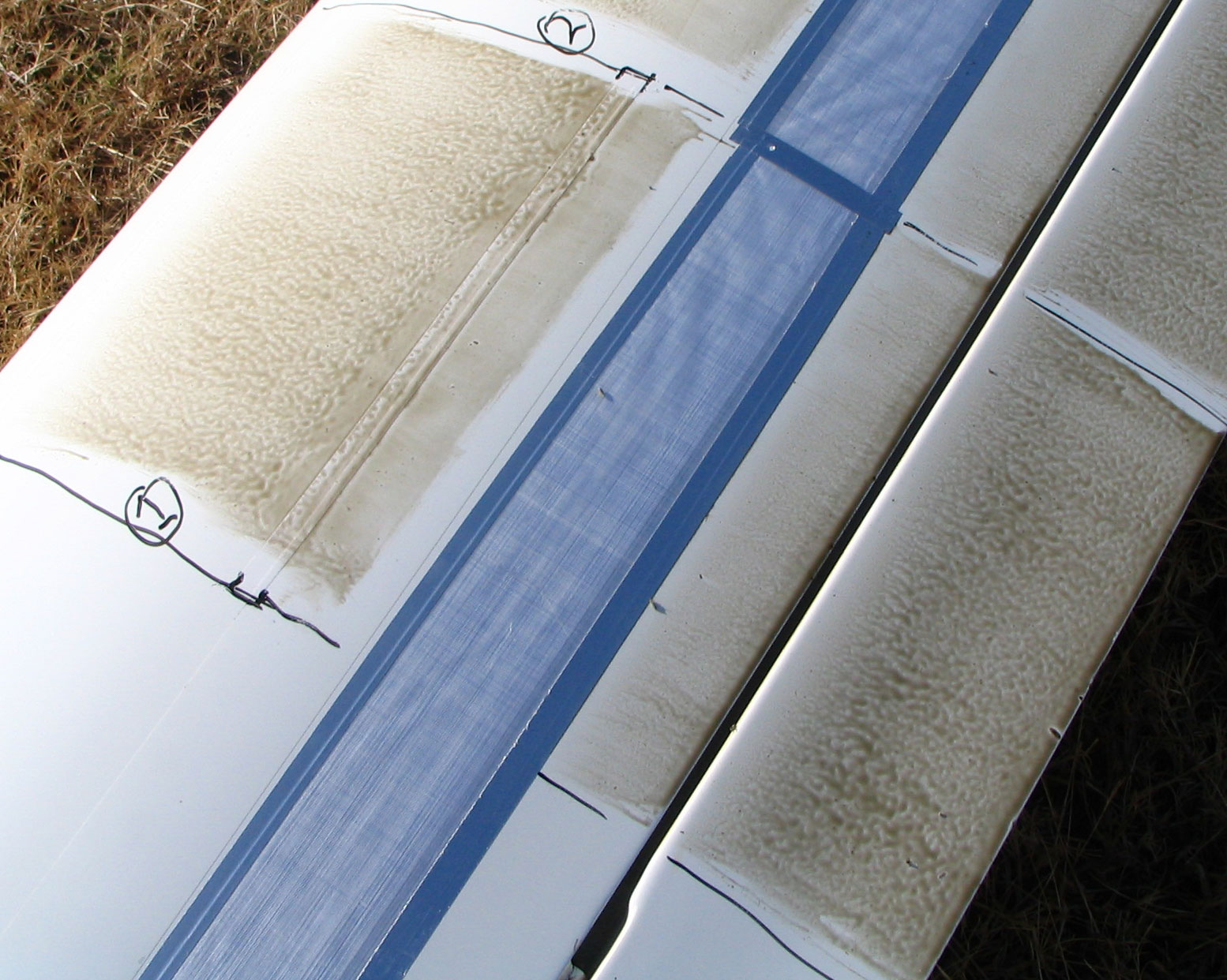
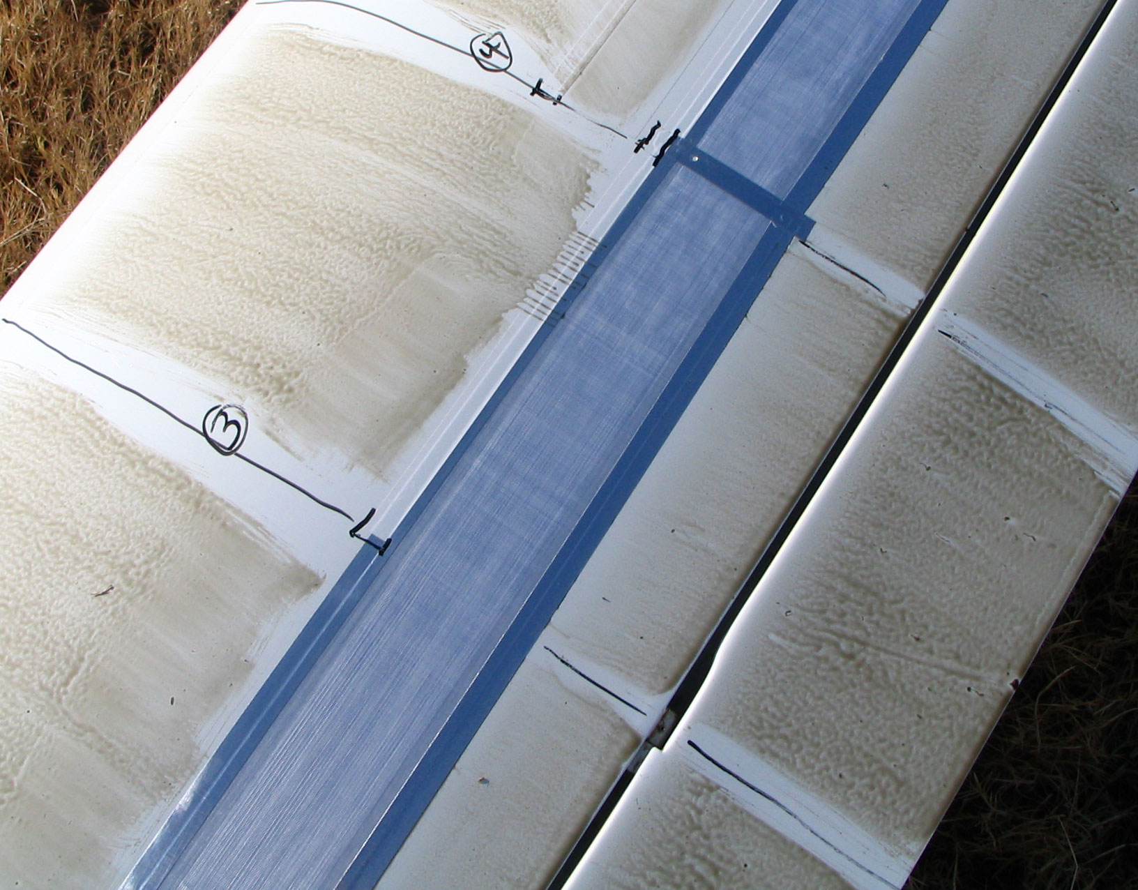
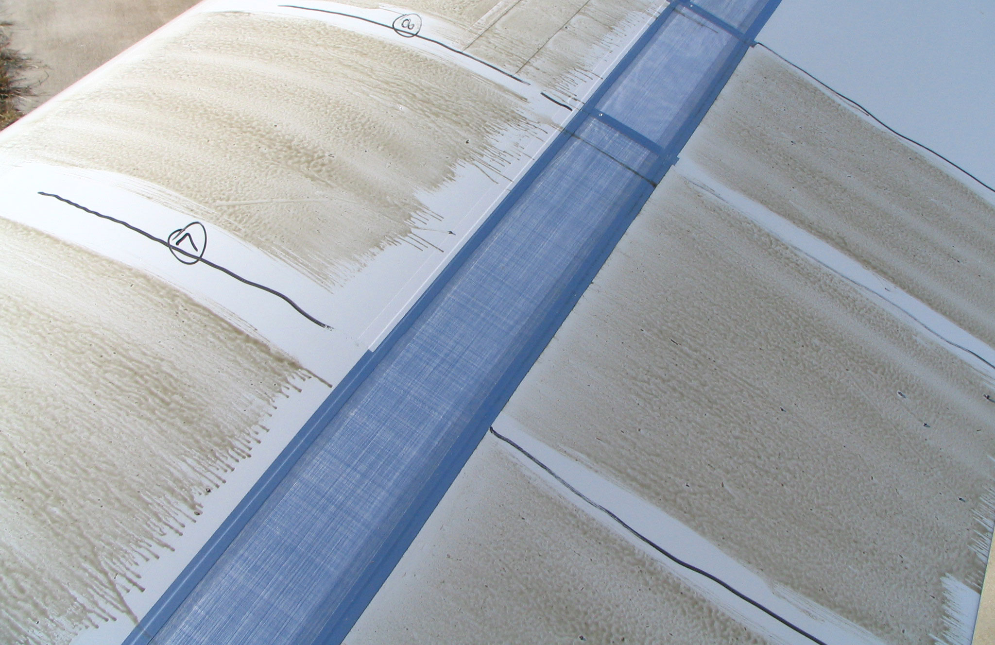
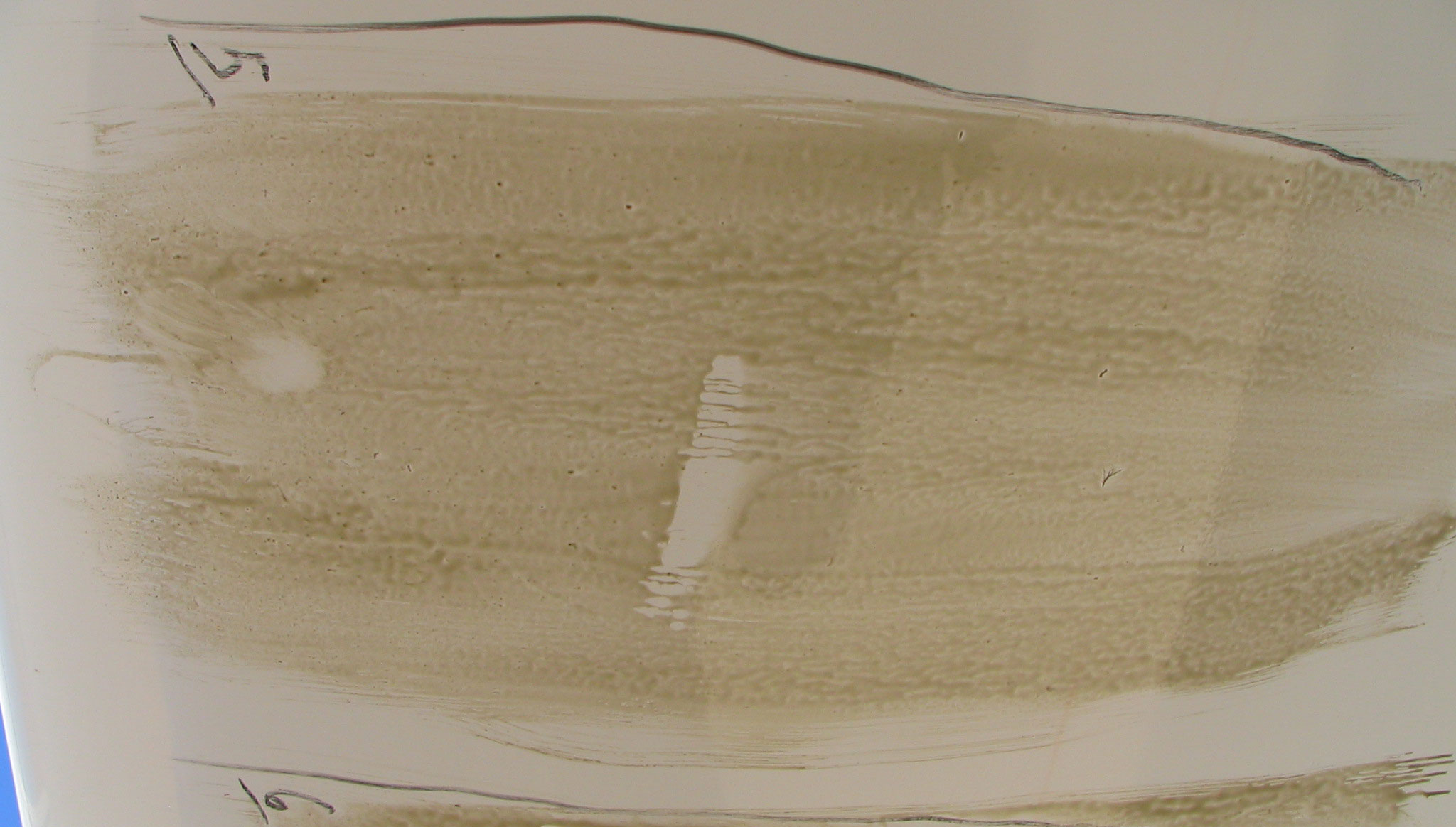
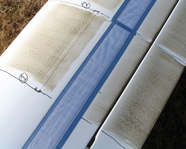
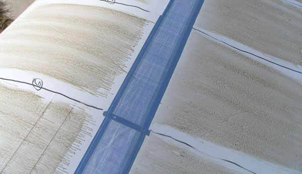
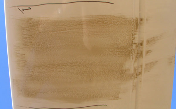
| After Flight - Top Side - Section 1 |
|
|
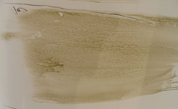
Intermediate tape with Tesafilm leading edge smoothing tape.
Deturbulator with unsmoothed leading edge.
The laminar detached area shows separated flow close enough to influence the oil without dragging it in streams.
Oil collected at the rear of the smoothing tape over the leading edge of the intermediate tape shows that
the flow in that region is moving backward. There is a clear line where the forward flow in the
bubble meets the onrushing detached flow. The absence of a thick line of collected oil at the front of the bubble,
as occurs on the unmodified wing, indicates that the flow in the modified bubble is moving very slowly.
|
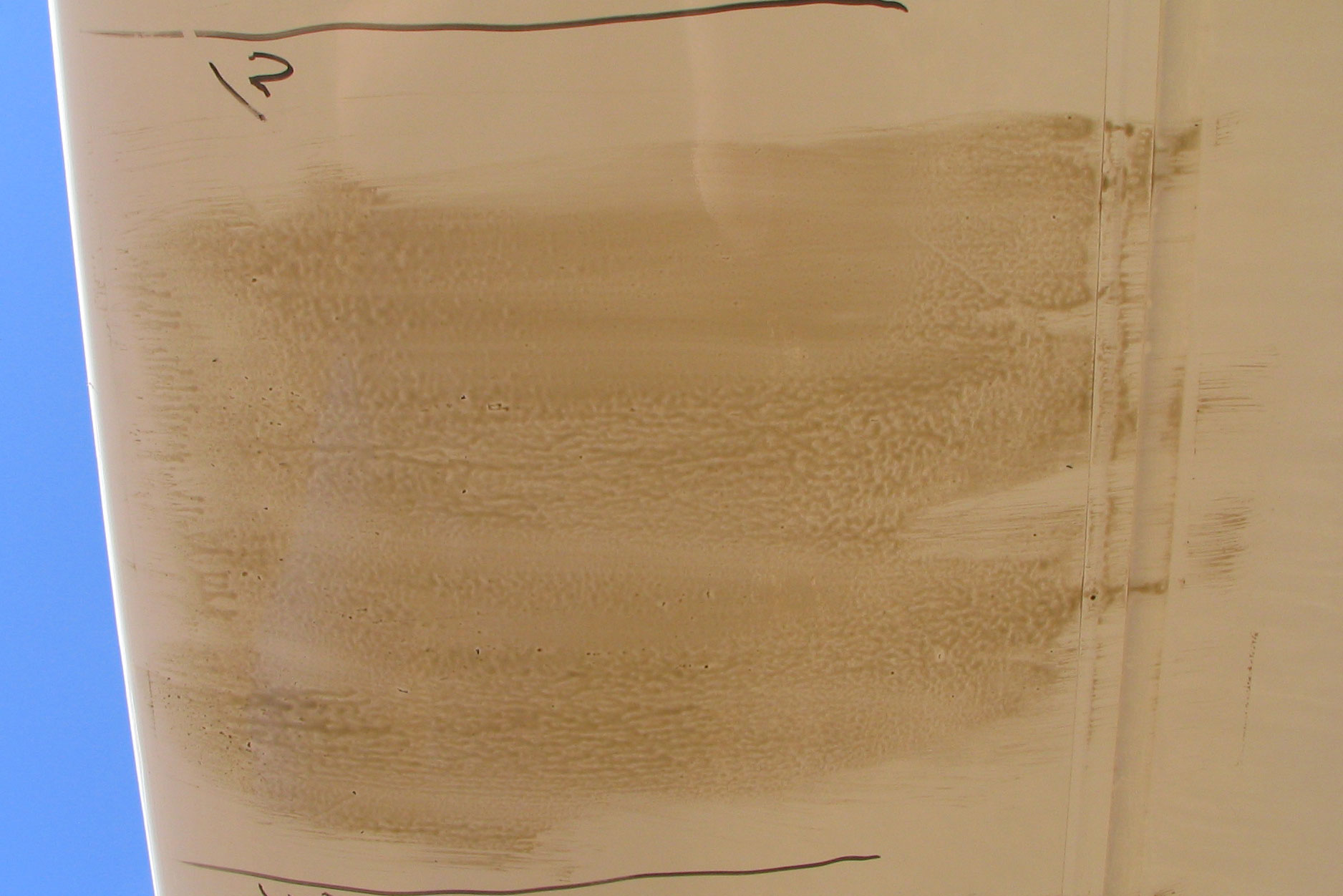
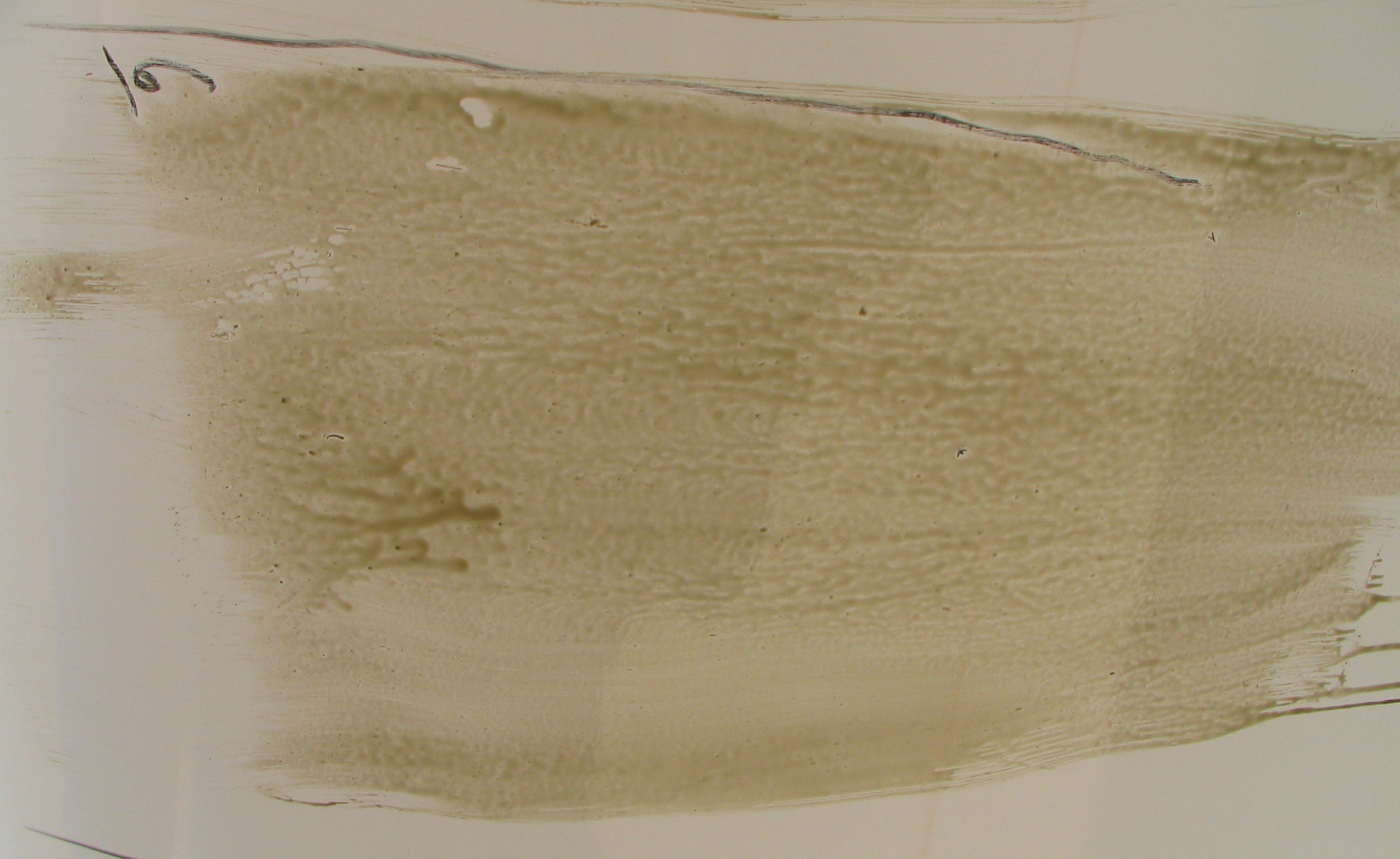
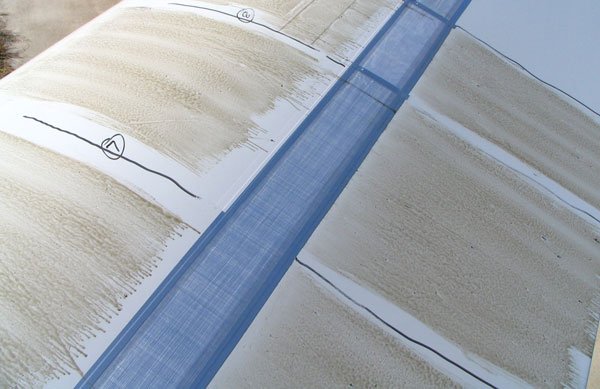
| After Flight - Top Side - Section 2 |
|
|
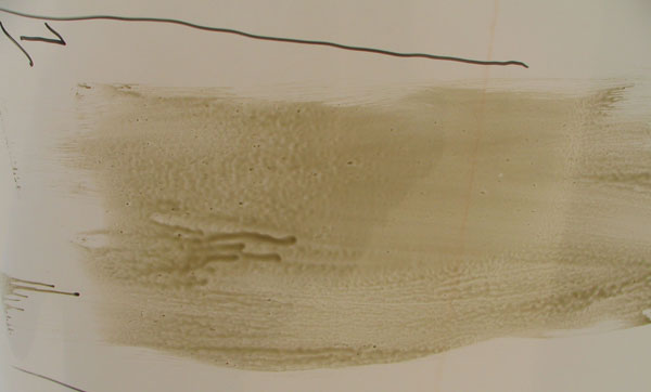
No intermediate tape.
Deturbulator with unsmoothed leading edge.
This pattern looks pretty good even though the leading edge of the deturbulator is not smoothed.
The circulation bubble is broad and has a curious, sharp, bright line where it meets the onrushing detached flow.
I do not know what to make of this feature.
Behind the deturbulator, the flow scrubs the surface too much and detaches only behind the leading edge of the aileron,
where it detaches nicely and shows no evidence of a trailing edge separation bubble.
|
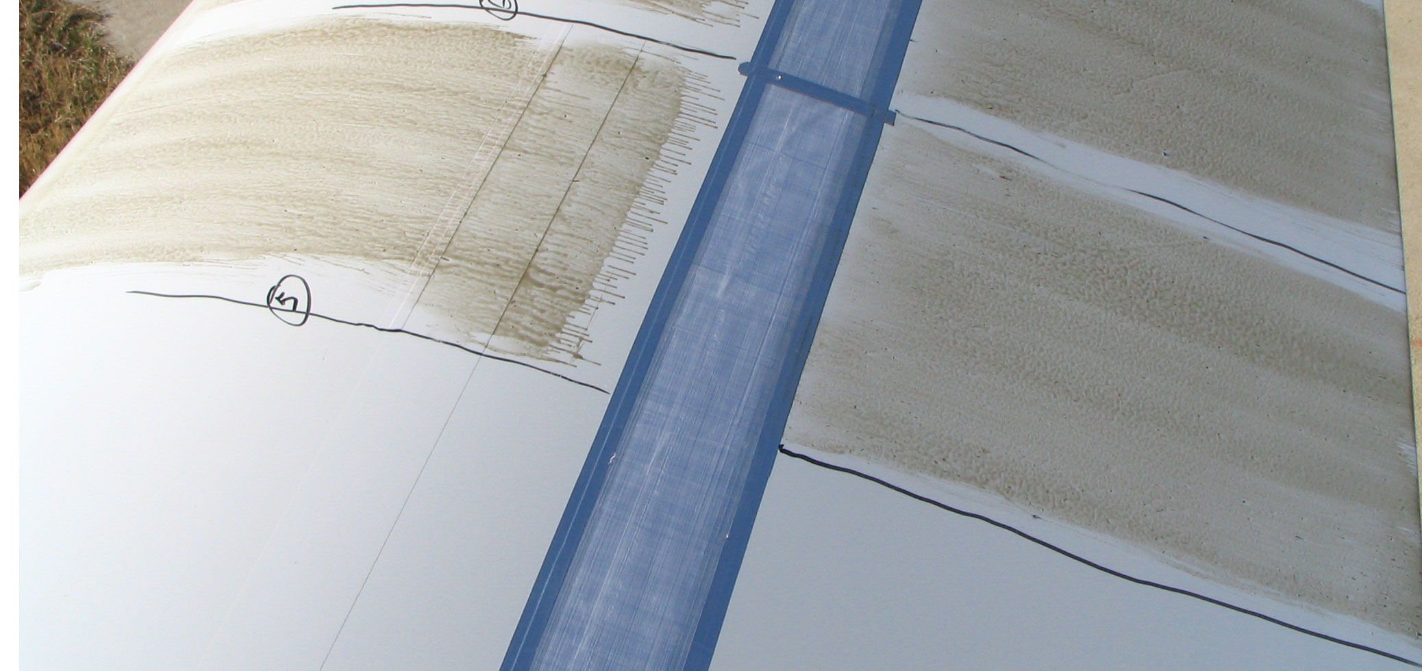
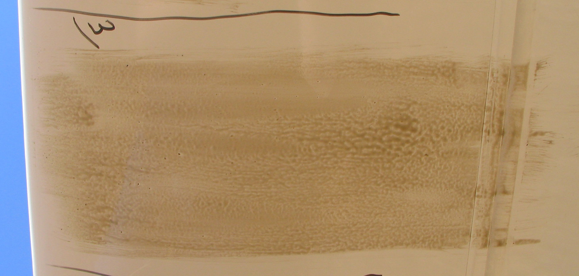
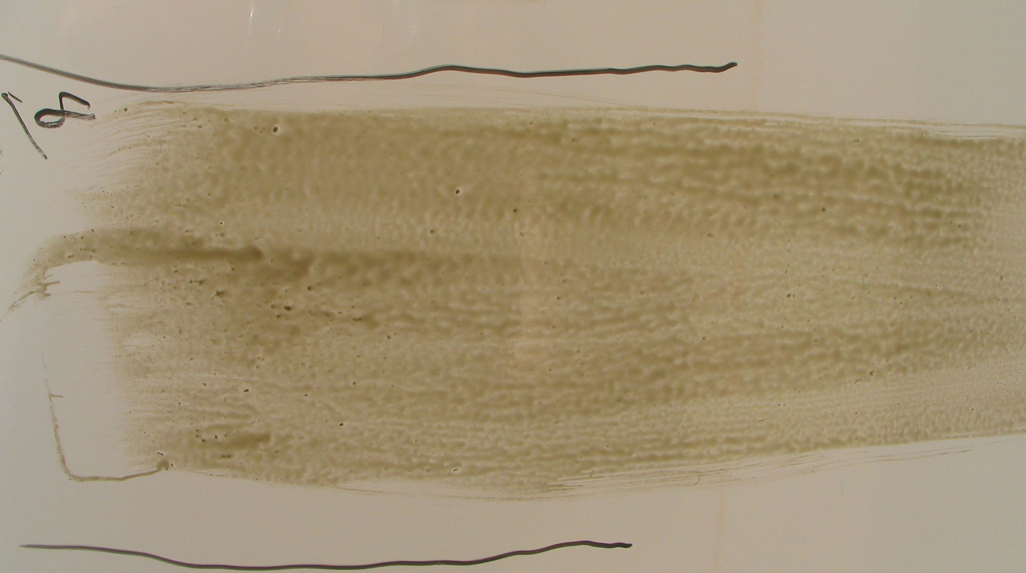
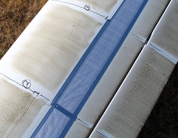
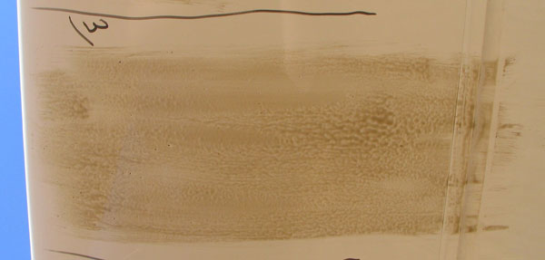
| After Flight - Top Side - Section 3 |

|
|
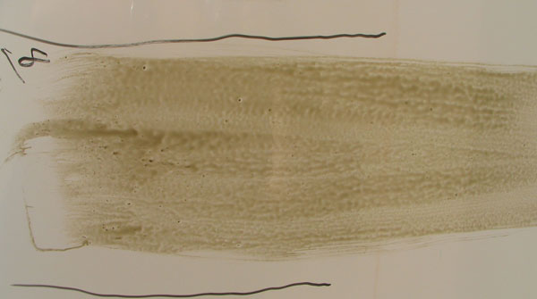
No intermediate tape.
Deturbulator with Tesafilm leading edge smoothing tape.
Smoothing the leading edge of the deturbulator makes little difference, except for evidence near the top of the image
where the flow appears to return close enough to the surface to stream the oil. The streams over the smoothing
tape suggest that the flow has been tripped.
It is curious that the sharp line between the bubble and onrushing flow in sections 2 and 3 are angled so that the bubble
is widest between the two sections. The only feature I see that can cause this is the edge of the smoothing tape at that point.
|
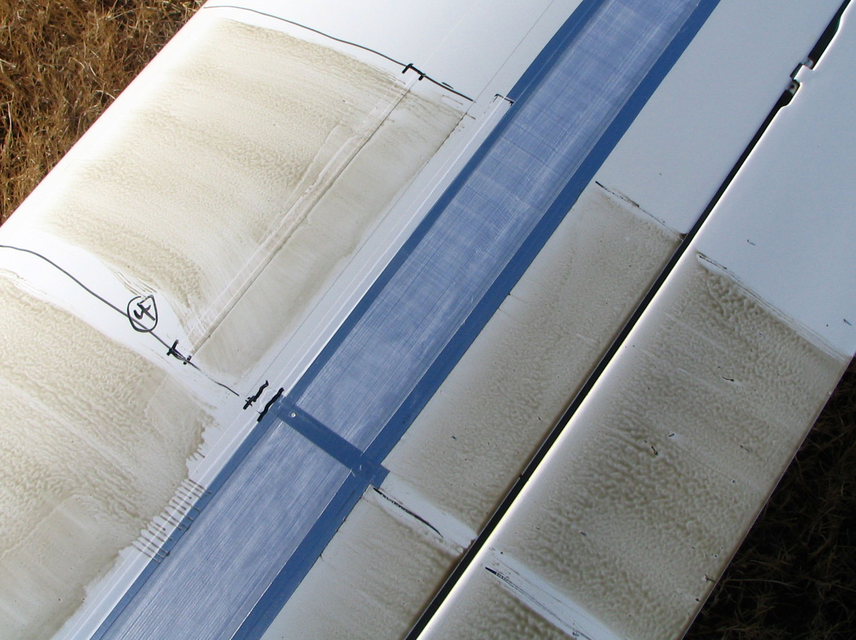
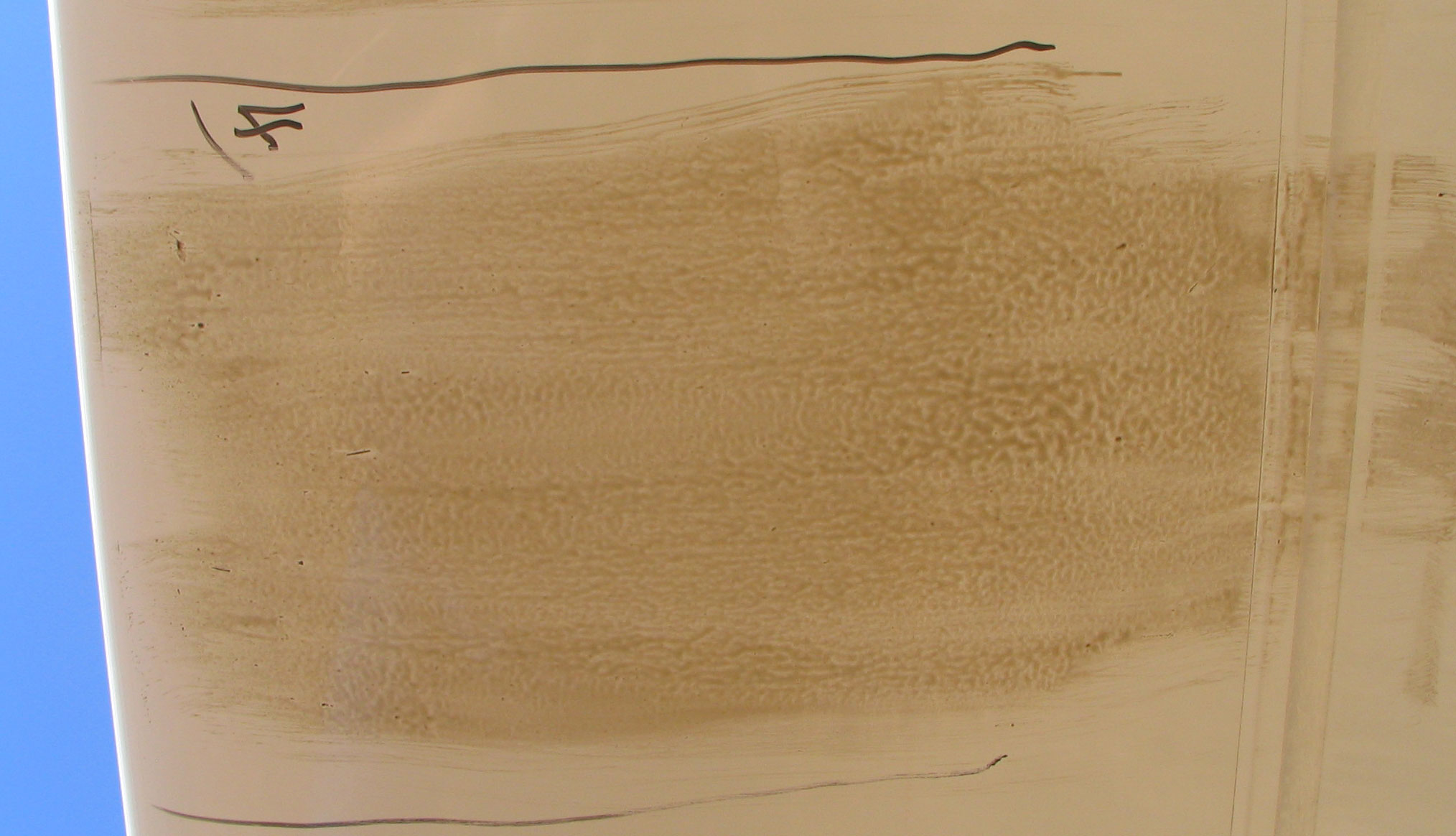
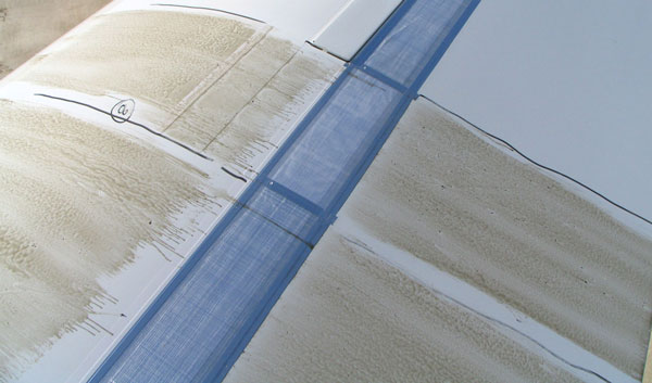
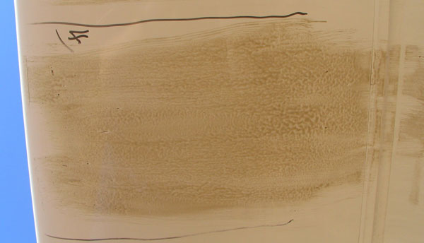
| After Flight - Top Side - Section 4 |
|
|
Intermediate tape with Tesafilm leading edge smoothing tape.
Deturbulator with Tesafilm leading edge smoothing tape.
This section resembles section 3. There is a strong curvature in the flow around the label 4 written with dry erase marker.
I suspect that this is influenced by the edge of the smoothing tape over the leading edge of the intermediate tape.
Also, there must be some influence at this span position from the joint between the deturbulator panels.
|
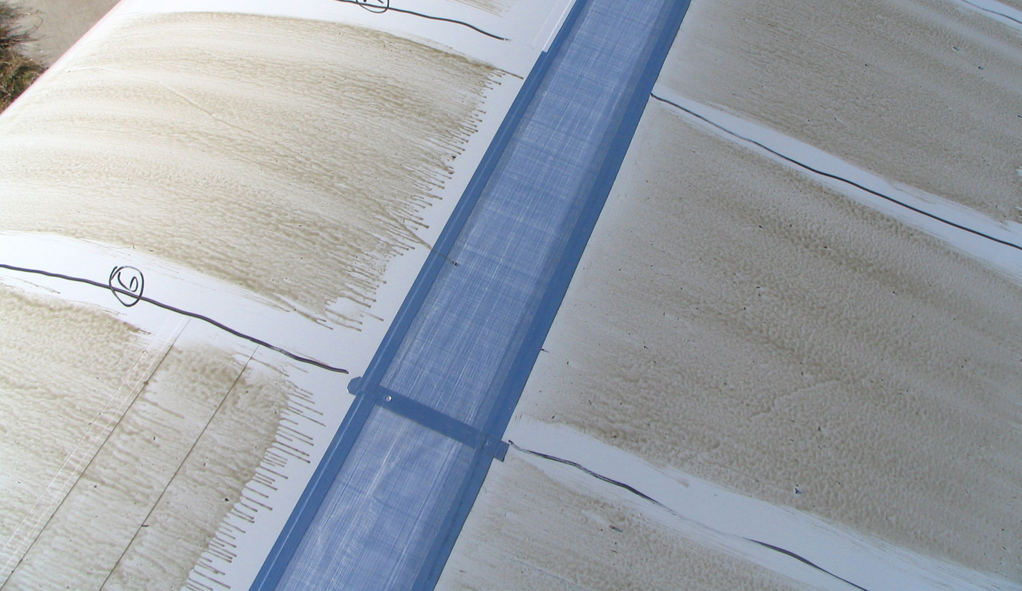
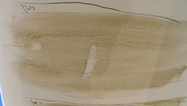
| After Flight - Top Side - Section 5 |

|
|
Intermediate tape with Tesafilm leading edge smoothing tape.
Deturbulator with unsmoothed leading edge.
Again, as seen after the 50 kt flight, the inner wing airfoil shows the flow approaching the surface gradually
ahead of the deturbulator, wiping out the transition bubble. Streaming of the oil immediately ahead of the deturbulator
is a clear indication.
|
| After Flight - Top Side - Section 6 |
|
|
No intermediate tape.
Deturbulator with unsmoothed leading edge.
Without the intermediate tape, the flow still approaches the surface ahead of the deturbulator. The end
of these runs suggests that the thickness of the deturbulator causes the flow to rise away from the surface
before striking the deturbulator.
|
| After Flight - Top Side - Section 7 |
|
|
No intermediate tape.
Deturbulator with Tesafilm leading edge smoothing tape.
Smoothing the deturbulator edge seems to lessen the shallow dip in the flow ahead of the deturbulator.
|
| After Flight - Top Side - Section 8 |
|
|
Intermediate tape with Tesafilm leading edge smoothing tape.
Deturbulator with Tesafilm leading edge smoothing tape.
|
| After Flight - Bottom Side - Section 1 |
|
|
Detached flow a few inches from the wing leading edge is indicated by the end of thick streams.
No evidence of flow in contact with the surface. No evidence of a transition bubble!
This is remarkable considering that there is no deturbulator on the bottom surface.
Only the rear edge of the wing's leading edge tape and the modified flow over the top surface can
account for the greatly modified flow over the bottom surface.
|
| After Flight - Bottom Side - Section 2 |

|
|
Ditto.
|
| After Flight - Bottom Side - Section 3 |
|
|
Ditto.
|
| After Flight - Bottom Side - Section 4 |
|
|
Ditto.
|
| After Flight - Bottom Side - Section 5 |
|
|
Ditto.
|
| After Flight - Bottom Side - Section 6 |
|
|
Ditto.
|
| After Flight - Bottom Side - Section 7 |
|
|
Ditto.
|
| After Flight - Bottom Side - Section 8 |
|
|
Ditto.;
|
Jim Hendrix
Oxford Aero Equipment
|