|
|
Humidity Dependency of Upper-Surface Leading-Edge Tape Effect (revised 2/10/2012)
|
For a full report, including an overview of the concept,
test data and a simple explanation of how it works, read
The Deturbulator Tape (PDF).
For more information on prior Deturbulator tape experiments, see
Leading-Edge-Tape-Only Performance Measurements
and
Effect of Leading Edge Tapes.
Cleck here for a summary presentation of this material in PDF format. |
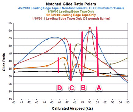
Fig. 1 shows four partial polars that demonstrate the effects on performance of a leading-edge tape (Effect of Leading Edge Tapes ). Each has the same shape with the curious "notch" near best L/D speed. The notch is centered on 49 KIAS, for the three oldest measurements, and on 52 KIAS for the last one dated 1/15/2011. The reason for the difference appears to be a reduction of 34 pounds in the glider's all up weight. These notches are absolutely consisent when no deturbulator panels are on the wings or when the panels are not working. Their cause will remain a mystery until someone is able to model the performance effects of the leading-edge tape. I have a hypothesis, but it will have to wait to be verified or disproven.
The reason for the wide variations of the amplitude swings of the four curves needs to be investigated. The differences are just too large to be written off as experimental error. This article is an attempt to find an answer in existing data, in the hope of learning how to install leading-edge tapes with consistent results from glider to glider.
The fact that all four polars have the same shape, except for the amplitude of the performance (L/D) swings, suggests that the measurements are real and that there must be a dependency on some as yet unnoticed variable. Air density is not likely an issue since the measurements are vs. indicated, not true, airspeed. So there is an automatic adjustment, since the same stagnation pressure exists, regardless of the altitude at which the measurements were taken, for each speed. Although I may be overlooking something here, I moved on to consider humidity. Since the glider was not equipped with a humidity sensor, it was not possible to have accurate readings. Nevertheless, the general atmospheric conditions as a function of altitude are available in archival weather sounding websites and these include relative humidity. So, I measured the glide ratio delta from the bottom of the notch to the highest peak on either side of the notch for each of the four notched polars. These are depicted as pink vertical lines that are labeled A, B, C and D in Fig 1 below.

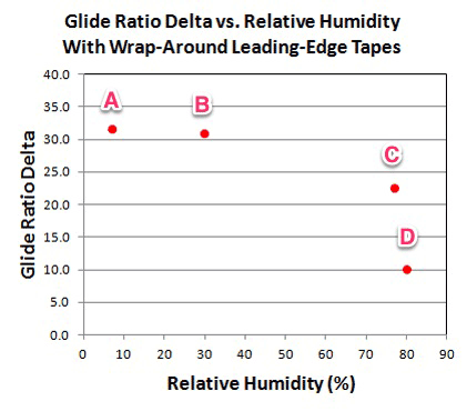
Relative humidity readings as a function of altitude were found on the same days as the flight tests. Three of these were taken at Little Rock, AR, about 80 miles to the west of the glider port where the test flights occurred. One was taken from Jackson, MS, about 150 miles to the South. These distances put uncertainty in the results; however, the apparent dependency is so strong, that using the regional relative humidity aloft seems to be close enough to point out a real dependency. These are plotted in Fig. 2 below.

Assuming that Fig. 2 illustrates a real dependency on relative humidity then the question becomes "why?" We think that the leading-edge tape performance effect derives from the rear-facing step at the rear edge of the tape causing a premature, marginal detachment of the forward laminar flow that allows it to accelerate in the strong negative pressure gradient without being retarded by surface friction. For this to occur, it is necessary for the elevated (.0025") flow, coming off the rear edge of the tape, to apply a shear gradient on the underlying air layer. This requires viscosity to enable the shear forces and surface friction on the wing surface behind the tape. The question is which of these predominates in causing the sharp reduction in performance swings with rising humidity.
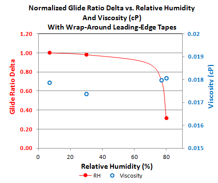
It is known that air viscosity falls off with increasing humidity. To see if viscosity is the issue, I calculated the viscosity using the regional relative humidity and the mean altitude and air temperature for the data points around the speed of the notch. The results are shown in Fig. 3 below.

It can be seen in Fig. 3 that there is no evident correlation between the red (performance deltas) and blue (viscosity values) curves. I take this to mean that changes in air viscosity are not the cause of the loss of performance improvement with high relative humidity values.
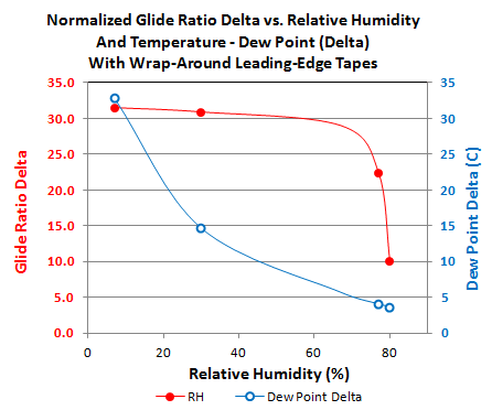
The second condition for generating a bed of vortical flow under the accelerating boundary flow is surface friction. There is no way of measuring this under the different flight conditions on the days when the data in Fig. 1 were taken. However, water vapor likes to adhere to surfaces and a reasonable way of seeing if this reduces surface friction sufficiently to affect performance, is to look for the dew point being close to the air temperature. If the two are only a few degrees apart, then it is reasonable to consider that, even without condensation, enough H2O molecules are adhering to the surface to effectively smooth it as seen by the air. Fig. 4 shows the air mean temperatures, when the points around the notch were measured, minus the dew point.

In this case, it is obvious that, for the two cases where the performance swing much smaller than normal, the dew point temperature was only a few degrees (C) lower than the air temperature. Furthermore, the temperature delta curve is monotonic and correlates well with the performance deltas vs RH. I take this tenatively as an indication that the mechanism by which high values of relative humidity cause a loss in leading-edge tape performance effects (upper wing surface only), is a loss of the requisite surface friction to put a shear force on the thin layer of air between the high speed laminar flow coming off the rear edge of the tape and wing surface behind the tape.
If this is indeed true, then it shows that there is a critical minimum of surface firction that is required to form and sustain a bed of vortical flow about .0025" thick behind the tape. And, although there is no humidity dependence on performance from the lower wing surface rear tape edge, there may be implications for wing surface preparation on both surfaces. It may be necessary to pay attention to ensure a minimum surface friction behind the rear tape edge and going back at least to say .5 chord.